a few thoughts about assembling bully, and other plateless/half-plate keyboards
Posted by zhol - February 17, 2023 ~ 3 years ago
hi, i recently rebuilt my prototype bully with a newer prototype PCB. i wanted to write the script for a build video, but I ended up building the thing before I did anything involving work. i have a few thoughts and suggestions for people, especially those who are new to soldering plateless builds. if you are planning to use a bully with a plate, you probably don't need to read this, but thanks for stopping by anyway!
your bully kit should arrive with the following:
- the case
- a pcb
- 1x 50mm JST-SH cable
- 1x C3 Unified Daughterboard
- some SKUF feet
- Geonworks Tadpoles
- 10x 50a durometer
- 10x 70a durometer
- Screws
- 4x M2x4mm screws (for daughterboard)
- 8x M2x6mm screws (for the case)
- test your PCB, and flash if necessary (it should not be necessary). the VIAL bin should be available in the geekhack GB thread, and you can compile from source from my fork of vial-qmk. To get the PCB ready for flashing, hold the reset button on the back of the PCB for three or so seconds while the PCB is connected to your computer over USB (this means plugging in the daughterboard over JST to the PCB), at which point dfu-util/qmk toolbox should recognize that the board's ready to flash. You may get some error/warning message about a libusb timeout, that's normal. unplug and re-plug the cable after flashing, or just press the reset button once.
- at this point, i would start off by installing either end of the 50mm JST-SH cable into the C3 Unified Daughterboard, and then install the daughterboard upside down into the case.

- lube and film your switches as necessary, or don't! i'm not your dad. assemble your stabilizers with whatever lube feels right wherever it feels right, and then install them into the pcb.
- now you can pop your switches into the PCB. soldering difficulty will be modified by your selection of switches based on how thick the PCB mount pins are. earlier PCB prototypes use vanilla marbastlib mx footprints, which have pcb mount pin diameter to cherry mx spec - 1.7018mm ± 0.05mm (spec sheet says 0.067" ± 0.002") for tolerance variance, which rounds down to about 1.75mm diameter. some manufacturers' bottom housing molds will be sufficiently thick to jam into the pcb without issue, but some may be on the looser end, perhaps as far as falling out if you flip the pcb upside down to begin soldering
these suggestions are based on my limited experience, ymmv, don't yell at me if you have better/worse experiences, and so on.
*** denotes extra tight fit with my samplecomfortably snug possibly borderline loose i have no idea jwk/durock (light tactile***, t1, penyu, alpaca, lupine, quartz) jwk/durock (pom, mm.switch) ktt winglatch 5-pin (haluhalo) huano gateron (black nylon bottoms***, cap v2, inks, geckos, baby kangaroos, zilents, yada yada yada) gateron (oil king, cj) haimu (cannonkeys heartbeat, geon, cbkbd trash) aflion cherry (hyperglides) kailh (midnight) leobog? tecsee (coral, purple panda, ice grape, ice candy, oreo, diamond, carrot) also tecsee (techno-violets, cow, ruby v2) ttc (hey) keygeek (raw) sp-star (duck, meteor white, yanyu) momoka (shark) outemu gazzew 5-pin meirun (no comment)
the production pcb offered in the CBKBD run of bully is manufactured with a slightly modified footprint that takes out the 0.05mm tolerance, and reducing the diameter down to 1.7018mm. this should be as thick as ai03's MX_V2 (which also use 1.7018mm pcb mount pin diameter) where the switches stay in the PCB extremely tight. but if you produce your own PCBs via JLCPCB, I think their mills or whatever weren't precise enough, and didn't notice any increased tightness in some prototypes I had produced. alternatively, maybe I goofed somewhere.
if your preferred set of switches are going to be on the looser side, you're going to have a bit more of an annoying time, but it is far from impossible; the second build with a prototype pcb was done with haimu switches, and only required a bit more patience! - alright, start soldering!
this is easier said than done, depending both on the switches, and the key location. the bottom row is a little bit looser in some areas due to the multiple layout options.
if all keys are on the looser side, I recommend getting all the keys into the front/face of the PCB, and then apply a hard and large surface like a book to press into the switches to keep them all steady as you flip the PCB over onto its rear to begin soldering.
if your switches feel tight enough in the PCB (like the switch's tightness can hold up the weight of the pcb), you can just solder straight into the PCB. if they're on the looser side, I recommend soldering only one of the pins on each switch first. this will help for a couple of reasons:
* sometimes a looser switch may not be inserted completely into the PCB when you solder it in. if a key is only partially inserted into the PCB when soldered, you can fix that by reflowing the joint while pressing the switch into the PCB; while the joint melts again, you should feel the key fit completely into the PCB, at which point you can remove the iron, let the solder cool, and then you can release the switch, which should be fully fit into the PCB.
* slightly looser switches may not be aligned perfectly. you can eyeball alignment issues, but putting on keycaps should help make it clearer where you need to re-align keys. i have a few business cards that I fold up and jam between the keys to provide some rigid alignment; re-flow the joint, and the card should help straighten the key out.
you may have to desolder a key here and there just to fix the alignment. don't worry too much, this happens from time to time, you can fix this, and this is a 40 so it's taken you five minutes to solder anyway.
* if you have one of those alignment forks, those will probably work fine - install tadpoles into the pcb. if you imagine the tadpole pin like a tadpole (the amphibian larval stage), you want the tail to face you, and the head to face away from you, towards the desk. alternatively, think of it like a screw going into the top of a top mount board.
the bully pcb offers 8 total mount points for tadpoles to be inserted. you can use all of them, you can use only 4, you can use tadpoles of all the same durometer or mix and match as you would like to.
earlier PCBs used 3.2mm holes, which lended to the tadpoles tending to fall out if it was not at rest, so production pcb's use tadpole holes with 3.0mm diameter. inserting the tadpoles, especially at higher durometer (like 90a) is a little difficult, so to make things easier, I recommend pulling the tadpole pin from the other side with one hand while using your other hand to push the tadpole in.
also, do take care that aggressive typing on plateless PCBs is more likely to experience switch pins bottoming out into the case, and an entire column of keys firing. inserting all tadpoles into the PCB provides the firmest typing experience (as far as plateless goes) and therefore most mitigations against bottoming out, but can maybe remove some of the typing vibes you look for. personally, I prefer the outermost two points on the top and innermost two points on the bottom, but it's your world, do what makes sense for you.
- [optional] some owners might be dissatisfied with the acoustics of the case that can sound a bit hollow towards the center. to deal with this, you can apply the "force break" mod, which means bully shares a pedigree of "kustoms" like the AR87 (per :3ildcat) that benefit from it. some people are into it, some people don't care.
- insert the other end of the JST cable into the PCB, and ease the PCB into the bottom side of the case. the cable being shorter than other boards means there's less slack to work with, but you should be fine.
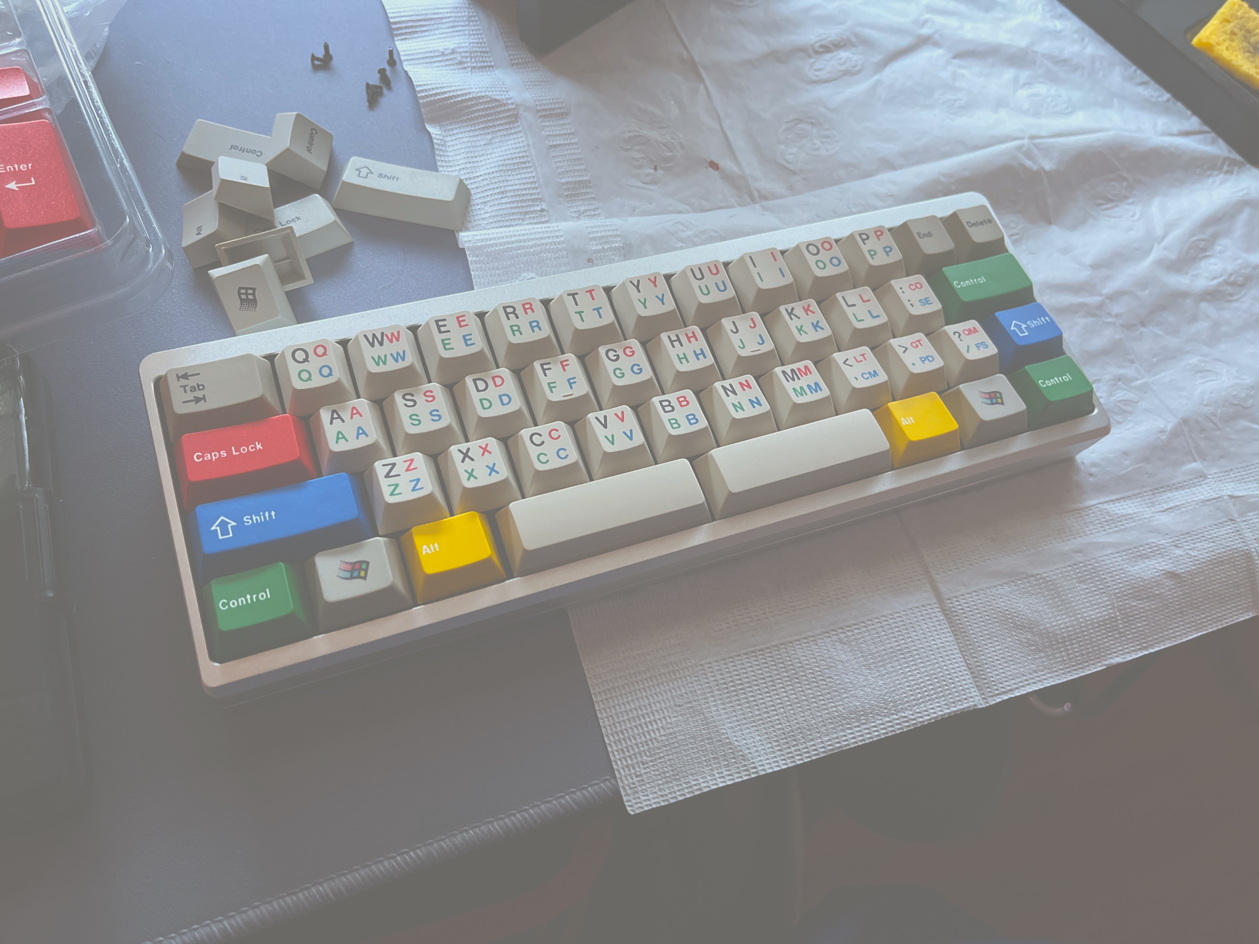
(left alt is unaligned, I fixed it later don't worry)
- push the top onto the bottom, which should ensure that the tadpole pins insert, friction-fitting into the top case. ensure the case lip faces whichever way you'd like it to.
- gently flip the board over, screw the screws into the case. at this point you can apply the SKUF feet onto the case bottom, if you haven't already

you should have a keyboard now! it'll probably take a few swings to see which tadpole config you like, but i hope you enjoy it.